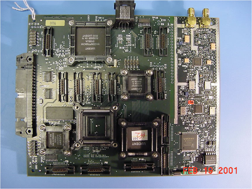
The Frist Generation Systems and Early Field prototypes - Circa early 2002
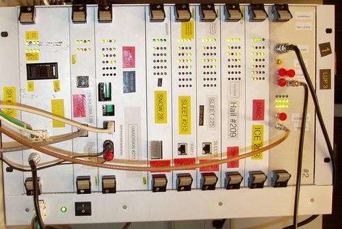
The prototype above is an FPGA prototype, using the biggest FPGAs available at the time. Given the speed of the signal processing and the uncertainties of the radio environment, there was not much choice but to implement the chips using gates instead of software. The use of FPGAs in the field was too costly. I think that based on COSSAP simulations we calculated about 3 Gigaflops of operations for the receiver, excluding audio and control. This meant that DSP or other processors would consume too much power, and this forced the choice of implementations. Things are different today and a multiprocessor implementation of the satellite system of this complexity possible in a single component, with an architecture of VLIW or other multiprocessor platform augmented by programmable hardware accelerators.
The company started the satellite radio program about 1998. I was hired to run the program in January 2001, so I have little history on prior events. The early prototypes were built by the time I arrived on the scene, but a lot of bad pres was had for being late. I was tasked with getting the program on track and keeping the relationship with the customer from degrading. While the program was technically on track based on the presentations reviewed more than a year earlier, the market was ready and the demands of the business were to launch service within a year. This was an interesting challenge which had to be surmounted.
Aside from the initial challenges of the business, the technology had its own difficult problems to be solved. The receiver, after all, had to receive three separate signals which experienced different time of arrival, Doppler, and had to be combined after demodulation but before error correction, making sure that the bad signal, in degraded conditions, did not anihilate the good signal.The energy per bit in the satellite link is low, because one wants to maximize the bandwdth, and the mobile nature of the service requires receivers that can track scintillating signals which vary greatly with foliage, or simply disappear under a bridge. All this made for interesting verification methods and receiver monitoring to understand what the environment was presenting to the receiver.
The complexity of the implementation was higher than any other broadcast system. The technical challenge of the project made it relatively easy to attract the best engineers to work on the effort, but the delivery of the technology would be a constant challenge.
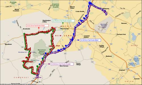
FIeld testing such a complex system is always critical, because the simulations cannot possibly cover the range and scope of the field conditions. This was especially true for a system which incorporates seconds of delay. To effectively simulate seconds of reception would take 20 days of simulations on the workstations at the time. I am sure this number has decreased, and compute farms can do this. But we investigated a number of functional logic simulations environment and found that the amount of effort was higher than FPGA. So, subsequent generations used FPGAs as well. The rack prototypes were verified using lab vectors, but the ultimate test would require us to tote the prototype around in a test van, and collect data.We collected a lot of field data, especially in neighborhoods with trees and railroad/road underpassses. This data would allow us to monitor 20 to 30 key receiver parameters and gain insight into the interactions between the receiver and the signal conditions.
In later years, we were able to capture the field environment and pump the sampled data direclty into a storage array. Corner case field conditions could be analyzed post capture and the corner cases could be reproduced in the lab, resolved, or simply explained as insignificant. This approach remains a powerful method for field data collection for any wireless network.
To summarize the challenges in such a receiver, we note that it had to:
One of the most challenging conditions were found when the satellite handed off to another satellite, as the descending satellite dropped below the horizon and the ascending satellite rose, at least one signal came in at low elevation angle was vulnerable to obstacles, trees, trucks.
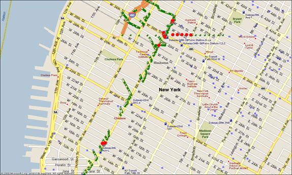
Manhattan test route used in system prototype deployments. The test systems were designed to gather key receiver health parameters and measure them. These parameters were logged into cery large files, along with the radio environment experienced by the receiver. In subsequent generations, this data gathering was done within the chip and was available on one of the interfaces. The information could then be piped into MatLab and used to define improvements, changes to parameters, or changes to software.Notice that the GPS was not happy with the urban canyon (the van was driving straight!) . This is one of the toughest radio environments in the world.
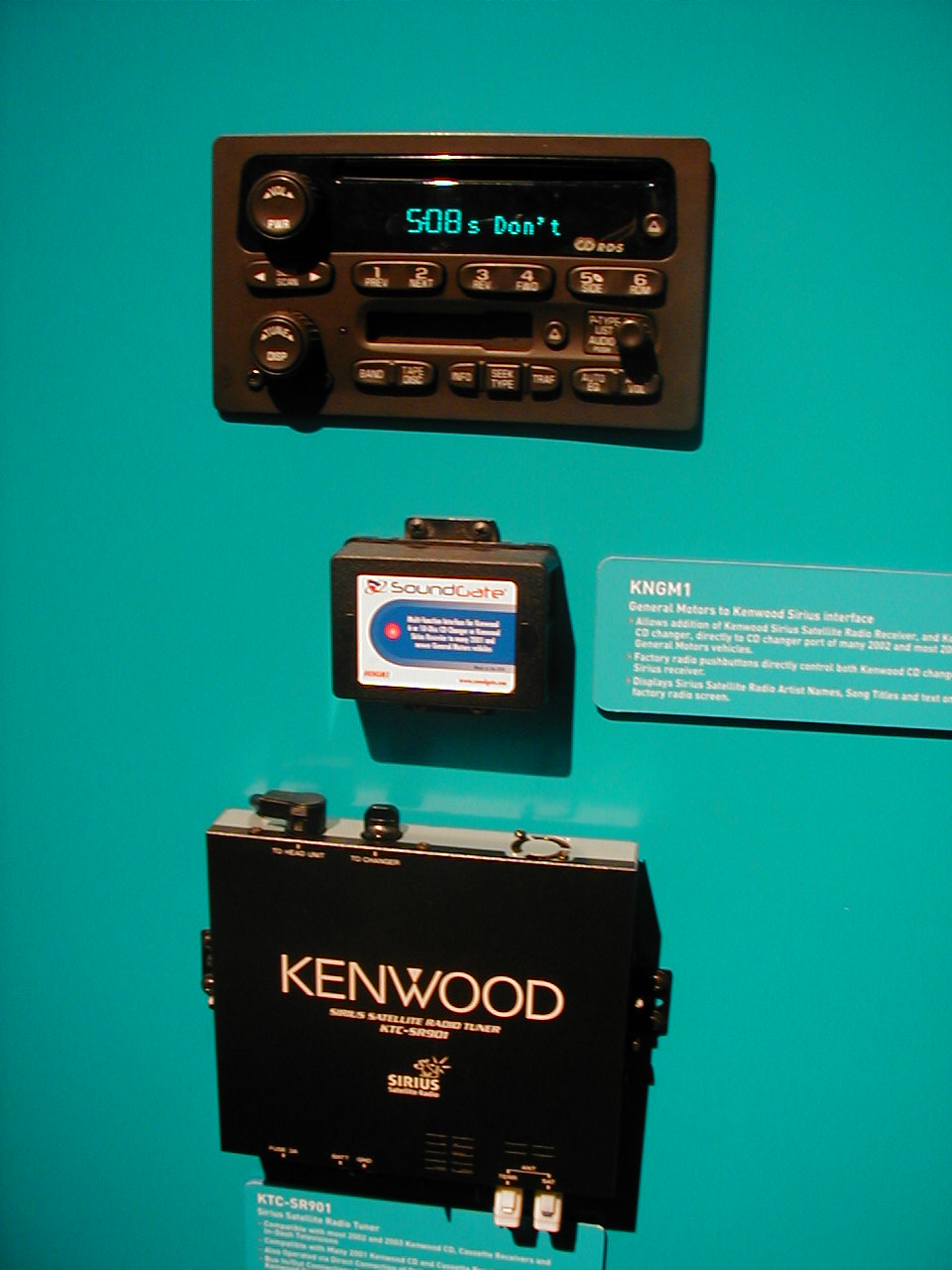
A typical Radio installation suing first generation chip sets, consisted of a DLP (Downlink Processor), and a head unit. The DLP contained the complete receiver except the antenna, and communicated with the dashboard radio through a control bus. The user interface was in the dashboard radio.
A typical corner case where the terrestrial signal is mostly missing. Decoding in such conditions is very difficult.Pilot carriers help.
l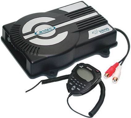
This First Generation, aftermarket receiver, placed the user interface in a very large oversized microphone style control head, with the core of the receiver mounted under the seat. The first receivers burned close to ten watts.
Chip Evaluation Board
What it does: