2009- Complete Refit of a 49ft Wauquiez Centurion Yacht
I hope this page will dispell the preconceived notion that Yacht owners live a life of luxury. WHile true for the very rich, for most of us this is a passion which requires work, and one cannot be afraid of this work and own a boat. Of course the amount of work described is beyond normal, but I hope you will find it interesting.
Itook delivery of the boat in June. I knew the boat needed some work, and had planned to leave within six weeks after repairs started. The planned repairs took two months. The unplanned repairs took another 7 weeks. To call this a complete refit is a misnomer,, because such a task is never done as new problems and new efforts are made to bring the yacht to top conditions. I firmly believe the yacht is one hundred percent offshore capable presently, and what remains are cosmetic problems, storm contingency gear such as a storm jib, and arches and dodgers for cruising..
I started the work after creating the corporation which could stand separate. The work schedule would consiste of 12 hour days, 7 days a week, for a period of 3.5 months. Somehow, I concluded that the work in corporate life is a lot easier than the daily physical effort of a naval yard. I seldom felt so tired on business trips and world roadshows for my business work, as I did during the summer of 2009. I had occasional, welcome help from great friends who generously donated their time.
The project was a welcome break from corporate life, but it was arduous and requireed incredible energy and stamina. I lost 10 lbs, though I was already fit, and the project management aspects for such a project are tremendous if you do everything yourself. Approximately 300 purchase ordersor work orders to the yard had to be coorinated. Orders ranged from a simple electrical connector to a 13,300 lbs keel, and yard orders ranged from rebuilding the keel stub to a simple touch up weld on the windlass handle.
In addition to the above, there were a number of small projects which filled up the evenings, such as refinishing the cockpit table, or intalling a windlass remote controller, or replacing a Fuel Guauge for the engine.
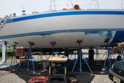
WIth the boat arrived in the yard, a couple of days of heavy rain delayed our removal of the 1,000 lbs mast. Once the mast removed and stored, I ground away the fairiing compound around the keel stub interface, and backed off the bolts with a four foot torque wrench. The boat was lifted with a travelift and blocked up on two foot timbers and stabilized on jack stands. It would stay this way for nearly two months while work was performed.
The bolts, thankfully, removed without ceasing. Stainless steel has a tendency to gall if not lubricated properly. Naval architects recommend an antiseize compound based on nickel, for marine environment, but this was not applied at the factory and I estimate 600 ft-lbs of torque were needed (~two strong guys on a 4 foot torque wrench or breaker bar. A friend helped. Wen the bolts loosened, it sounded like a gunshot.
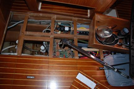
Already the mess on the inside of the boat starts, clutter sets in with tools, supplies, and repair materials lined up. Notice the 48 inch torque wrench.
Bottom Stripping the old bottom paint using a chemical non methylene chloride based stripper. The chemical is safe for fiberglass, non-alkali, but requires a long soak time to take effect. About 20 years of paint were removed.
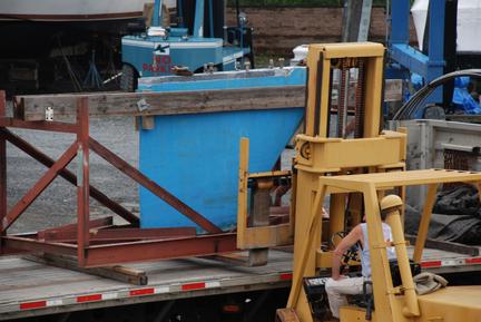
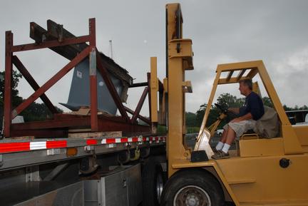
The old keel was loaded on a flatbed. It would be replaced by a 13,300 lbs bulb keel which keeps the center of gravity of the boat at the same point, to ensure the righting moment and fore/aft level trim is not affected. The purpose of the project was to reduce draft from 8'8" to 7'0" so the boat could enter shallower waters safely. I avoided the temptation to further reduce draft, as some owners did (5'5" or 6'0" would have compromised the sailing performance too significantly).
c.jpg) Keel Design: Ed Dubois, Naval Architect, normally tackles much more complex and complete yacht designs than the re-design of my keel. I spoke with Ed over the phone to ask his advice regarding shortening the keel and designing an add-on bulb that would be retrofit to the existing keel. Ed advised against this approach as too much of a compromise in the sailing performance of the boat. Since he was the original designer of the Wauquiez Centurion 49, I am certain he was correct in his assessment. He graciously made available to me the design of a shorter keel, bringing a 6 foot draft. I thought this was too short and that the performance compromise would be too much. I decided to go with a 7foot draft, which meant redesigning another keel. On the plus side, the rudder would not have to be shortened.
Keel Design: Ed Dubois, Naval Architect, normally tackles much more complex and complete yacht designs than the re-design of my keel. I spoke with Ed over the phone to ask his advice regarding shortening the keel and designing an add-on bulb that would be retrofit to the existing keel. Ed advised against this approach as too much of a compromise in the sailing performance of the boat. Since he was the original designer of the Wauquiez Centurion 49, I am certain he was correct in his assessment. He graciously made available to me the design of a shorter keel, bringing a 6 foot draft. I thought this was too short and that the performance compromise would be too much. I decided to go with a 7foot draft, which meant redesigning another keel. On the plus side, the rudder would not have to be shortened.
 Manufacture of the Keel: After breaking the sand mold, the keel is hanged for two days for cooling.
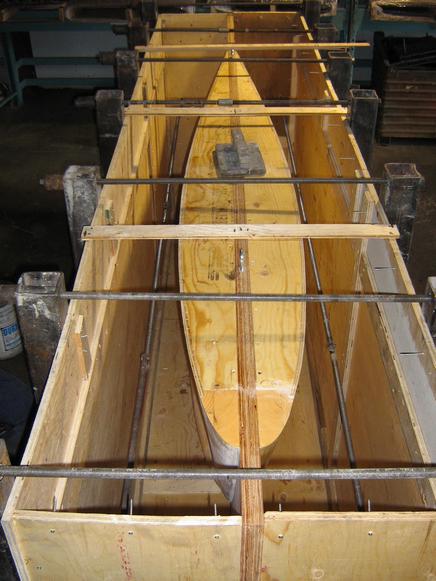
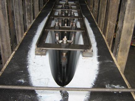 Manufacture of the Keel: The sand casting halves are joined and held in place by a steel structure. The threader rods serve two purposes. They attach the keel to the keel stub and they are welded together into a reinforcement frame acting as an armature for the lead, which is strenghtened by the addition of antimony (PbSb alloy) but nevertheless needs support. The frame holding the rods is a template.
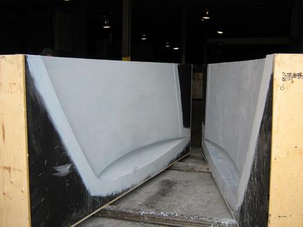
Manufacture of the Keel: Once the mold form is in the mold, a sand casting is set around the mold and coated with proprietary coatings. The sand mold can be separated from the form at the parting line. The result is shown.
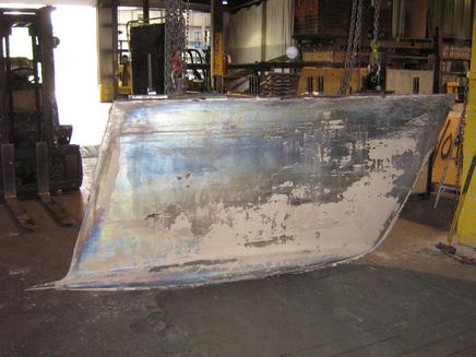
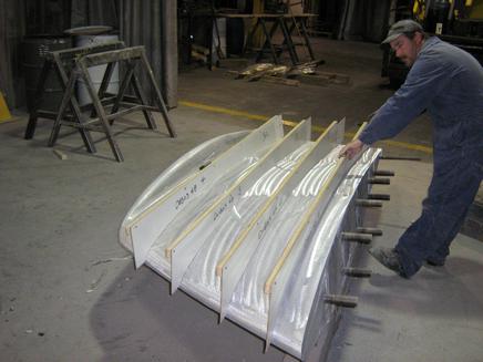 Manufacture of the Keel: The finished product has been ground to comply with the design form, and is now being checked for accuracy by a quality control technician, using control templates built from the CAD drawings. I was very happy with the result and MARS keels program management, communications, and capabilities. I chose them because they had CAD/CAM capabilities and were more than an old fashion casting house. Though my keel would be manually built from CAD drawings, the knowledge and approach, in my opinion, permeate the rest of the company and this shows in their product and customer contacts. They built the keel in a record SIX WEEKS! This was unheard of, I was lucky that they worked so hard on the project and also that times were quite slow in the marine industry at the time..
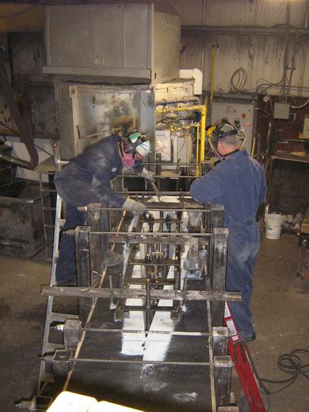 Manufacture of the Keel: Pouring the lead. The lead flows out of the chute pipe in the front of the keel. The alloy being antimony 3% and lead, the melting point is lower than the lead melting point of 327C, as the eutectic temperature is reached at 17% antimony (251C). It is about In any case, the energy needed to heat the 13,286 pounds of lead to say about 314 C, plus some margin for cooling (say 340C) is about 73kWH or 250000 BTU without taking heat loss in account. It is surprisingly a small amount of energy, this explains why the furnace is of a reasonable size. These guys have poured keels up to 100,000 lbs.
Manufacture of the Keel: MARS KEELS is a top quality supplier who built the keel custom to the design specs. The first step in manufacture is the form. The form is created with sections of aluminium closely fitted on sections of plywood which correspond to the cross sections of the keel in the CAD system. The sections are stacked at the distances required by the drawing as control points to create the 3D pattern, and the sheet of plywood on the center defines the parting line of the mold.
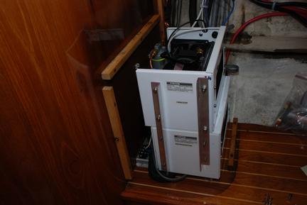
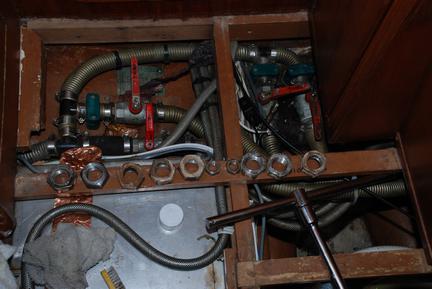
Refrigeration compressors: While the keel was built, the project was completed. The compressors fit nicely under the nav seat. Nicely, that is, from a cosmetic and room point fo view since they did not take space elsewhere. The fit was tight however, and special measures had to be taken: I built a coming to make sure the air came from the bilge and emptied into the cabin, and I had to put a lot of measurement and thought into the plumbing to make sure everything fit in this tight space. The solenoid on the floor level on the left had to be moved and two holes drilled in the panel to provide extra clearance and ensure enough ventilation space was available. In the end, it works great.
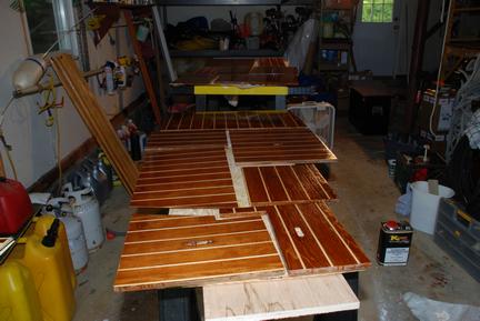
Floorboards: While the keel was being built, I stripped all the floorboards and revarnished them with a clear acrylic urethane medium solids varnish. This project filled the garage, and protective masks and a high cfm ventilation fan were important for safety. An autoshop setup would have been nice, however...
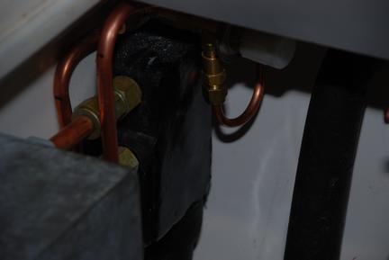
Refrigeration piping: The cold plates are etylene glycol filled plates with cooling coils to absorb the heat of the freezer and refrigerator. Both cold plates already had an extra set of coils to allow the refrigerator and freezer to cool the compartments. I routed the tubing judiciously and then evacuated the systemso as to avoid any moisture problems, especially if moiture had accumulated within the plates. Then I filled the system and voila. Cold soda and cold beer. I did have a failure, one of the axpansion valves did not work correctly and had to be replaced, the troubleshooting took a lot longer than the actual work of replacing the defective part. .
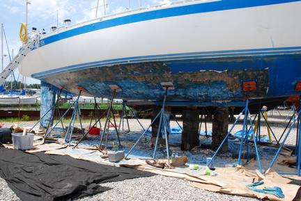
Removing the bottom paint also took place while the keel was being designed and built. Here the boat is shown with nearly all the paint removed, about 500 or 600 square feet of stripping, scraping, and sanding.
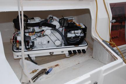
The generator arrived long before the keel, although after a minor delay This installation was also quite complex, with fuel lines being run to and from the unit to the main tank, and a complete new exhaust system, muffler, water intake system, and battery cabling complete with a new panel and kill switch. This would be like installing an engine in a small boat. It runs like a charm, it is quiet, and it will be very worthwhile on very hot days. Also, the A/C is a good way to dry the boat to reduce or eliminate rot in plywood over the next fifteen years.
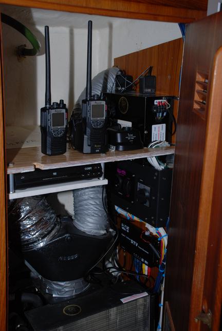
The custom panel for the generator fit neatly in the A/C compartment for the boat. I also added a shelf to place all the portable electronics, including GMRS radios, VHF, and someday satellite phone. This keeps the cabin clear of clutter (as long as I am not doing a project)
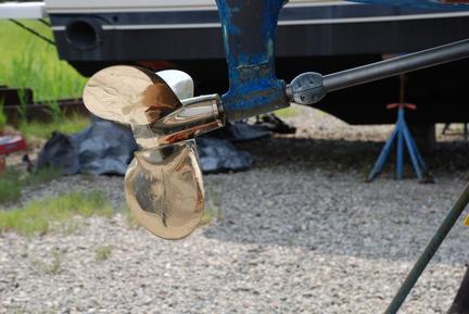
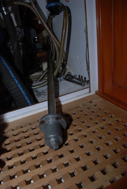
While waiting for the keel, I sent the propeller out for reconditioning. I removed the prop shaft, replaced the bellows and the stainless rotor in the dripless shaft seal, and changed the cutlass bearing. I ordered a new bearing from France-Helices since the part was metric. The shipping cost more than the part.
While I reassembled the propeller, I changed the pitch. THe boat was pitched wrong and the engine could not reach its specification RPM. THis meant too much torque and not enough RPM, the surveyor recommended to make sure the RPM was reached. Diesels have limiters and cannot exceed rpm specs, so being underpitched is probably better for the engine than being overpitched. This is the second maxpropped boat I own, and also the second time that the recommended pitch from PYI is wrong. But I love the product!
The new keel arrives. But more work to come, major work.
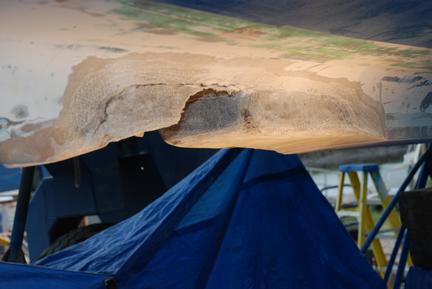
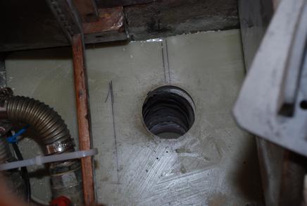
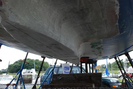
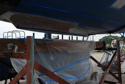
After we lifted the boat off the blocks, I noticed a crack on the bottom of the keel stub. The yard and I thought it would suffice to fill the crack and slap the keel on, but that some grinding was needed to ensure that the crack was filled properly. What was thought to be a minor cracked proved to be extensive water penetration damage to th epolyester structure. The laminate of the hull ad disconnected from the internal bilge laminates. Three days of fiberglass grinding and meeling ensued. The picture above shows the grinding half done. Additional grinding would take place to feather the layup on four separate days. The work filled about 80 gallons of debris. A tent around the boat protected the rest of the yard from nuisance dust.
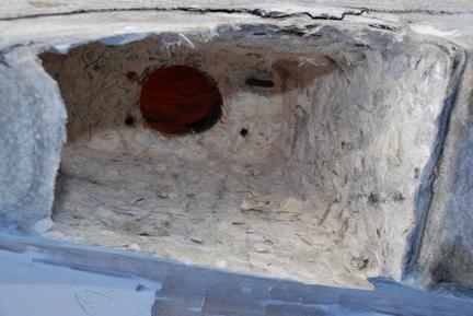
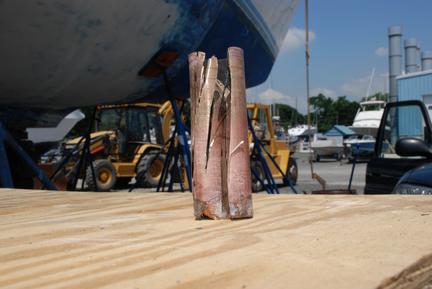
After grinding the outside surfaces the inside of the mast step was hollowed of its filler. The mast rests on the suface above and the filler had crept due to the 50,000 lbs compression of the mast. The attachment bolt for the keel was loose and this was the root cause of the damage. Tightening the bolt every coupls of years is critical, and a grounding may have caused some damage as well. The boat showed its age, with some fatigues problems. I doubt the keel would have fallen off for another five or ten years, but the boat is now like new.
c.jpg)
Inserted in the compression well below the mast step, these high density electrical boards have a compression strength of 10,000psi and are highly immune to water problems. They would provide direct transfer of compression loads to the keel instead of transferring the loads to the floor timber below the mast step. The naval architecture firm of Martin, Ottaway, Hemmen & Dolan was consulted and was very helpful in discussing possible solutions. Rick van Hemmen seems to know his trade well.
c.jpg)
After the first six layers of mast compression material was cemented with expoxy and microfibers fill, the interior of the mast compression well was built up and the boards were taped, Approximately 1/4 inch of fiberglass build up alone could hold the mast loads. Additional boards were added to complete the full height. Notice the discoloration of the glass on the side of the keel stub, and the peeled fiberglass which extended actually two feet from the keel stub .
.
This was an interesting project, but tough on the body and the mind.. and the wallet.But this boat is bigger, better, and tougher, than any new boat built for the price invested. An important consideration when in the middle of the atlantic.
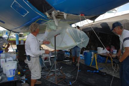
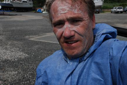
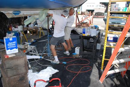
Fiberglass doctors at work. THere were four of us, including me. We wore protective clothing of course, but only when we had to since the heat was in the 90s. Extra slow cure epoxy would be used, and we would start around 7AM to prevent exothermic reaction from runing away. We did this for four days using te vacuum bagging as seen above. The supplies involve peel ply, blanket, and film, as well as two manifolds and a strong vacuum pump. Sealtape is a wonderful material that kept the air from leaking in. The bag vacuum reached 20 to 26 mm Hg. A vacuum regulator was not used.
Prior to starting this path I did a lot of research on materials and techniques. The key important take aways are:
Using Vacuum Bagging was critical since the construction technique call for unidirectional glass on the bottom of the keel stub, and the more fibers, the more strength on this critcal structure.
Epoxy has major drawbacks:: It takes a long time to cure and you can't build up layers fast. There is a reason people use vinylester to build boats cheaply, and epoxy /multiaxial laminates to build wind turbine blades. In fact, much of my laminate schedule was derived from wind turbine research from the 70s, and of course cleared with the architect. The price for strength is materials cost and labor costs, but it was important to maximize the strength achieved by the repair in the given available thickness.
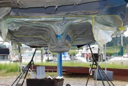
A completed vacuum bagging operation. The first day laid a schedule extending from two feet portside of the keelstub to two feet starboardside. Two layers of 18oz unidirectional, high strength S Glass, and two layers of Biax, spanned the whole width of the repair in one continuous strip. THe strips were overlapped for forward and aft strength. Unidirectional additional layers were placed on the bottom of the keel stub. The SGlass Unidirectional fabric provided fore and aft flexural stiffness in addition to the keel itself. The Biaxial fabric belt wrapping around the stub provided the athwartship torsional strength.
The laminate schedule: a half inch of biax added to the floor timber, which wraps around to the back of the timber and the keel stub. Afterwards, a high density epoxy milled fibers filler was used to adhere a slab of one inch thick G10 epoxy to the floor timber. The mast load is spread over a very large area, as the garolite board has a 55,000 psi compressive strength and huge flexural strength measured in mega-psi. The mast step is well secured in the G10 board using machine screws after drilling and tapping the G10 Garolite. Note the hole in the center, for socket and extensions access to the forwardmost keel bolt most inconveniently located below the mast! Yes, the Centurion 49 does have a keel bolt below the mast.
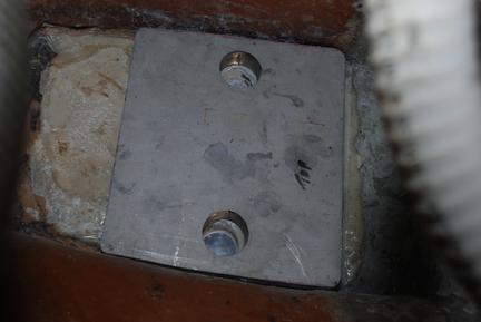
In order to further increase stength of the keel stub I added a schedule of reinforcements in the bilge area, including the floor timber on which the mast rests, and the forward bilge area subject to the highest keel loads and mast loads especially in extreme wind and sea situations. By using epoxy, further waterproofing would be achieved to ensure bilge water did not cause long term problems. THe backing plates previously found on the boat were only 1/4 inch in thickness, this proved very inadequate and slight creeping and distortion of the plates occured. The new plates, one inch thick 316 stainless, would allow the estimated rod load of 20,000 lbs to be distributed over many square inches, creating compressive strength of less than one tenth the compressive strength of the fiberglass.laminate.
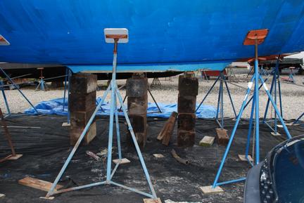
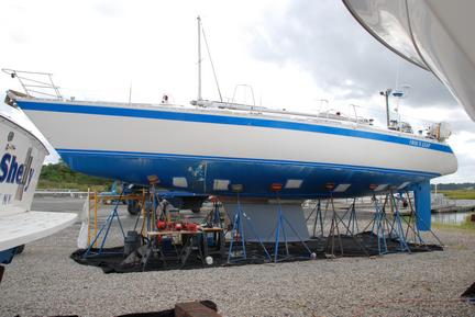
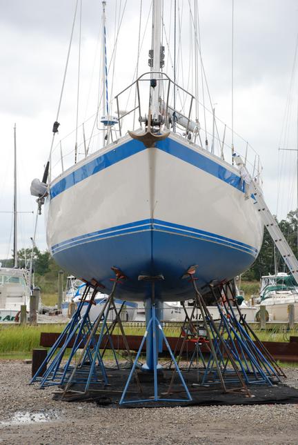
 Thirty jackstands were used to support the vessel while the keelstub was exposed for laminating and other repairs. Low load on the stands meant we did not risk damaging the boat for the last weeks where I needed access to the whole length of the stub to set its planarity.
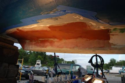
After the yard and I completed the vacuum bagging operation, I completed the rest of the keelstub by hand laminating anywhere from a half inch to three quarters of an inch of fiberglass on the stub. The end result was wider than the old stub, but the keel was wider as well. Several days were spent measuring angles and planarity of the new surface. The keel had to be perfectly aligned fore and aft, and also vertically, in order for the boat to perform as designed. The markings above, after the few days of hand layup, show the alignment marks, and the new hole location. I had no problems with the accuracy of the holes because a template had been built to match the new keelbolts. This template was used to drill the new holes. I ended up doing some grinding to fine tune the alignment, but it was very minor. The travelift was able to lower the boat right on the keelbolts after two minor adjustments to the keel alighment.
Ready for the mast.
After this picture was taken, sealant was applied to the new keel and the travelift lowered theboat to within a quarter inch of the keel. The next step was to torque all the bolts to spec. I did so with one of the yard owners, and the keel came up snug to the stub. A final torquing moved only five or ten degrees. This was a clear indication that we stretched the bolts to spec torque, but that the laminate was not yielding under compression.
Three people were employed in the caulking operation, as well as I. The travelift operator sporadically, one carpenter and two people spreading the caulk. When the keel was torqued and brought to the interface, the excess caulk was cleaned up by two people.
Multiple thin layers of fairing compound helps minimise turbulence. Since I used to race, I have a distaste for rough bottoms.
c.jpg)
The mast being lifted by a crane truck. While waiting for the keel, I had rewired the mast, changed the antenna, and added an anchor light because there was none, supriisngly.
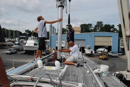
A very tense moment, handled quite well by a very professional crew. After two tries one of the shop machinists came and looked and asked me if I was certain the mast step was in the right orientation. I told him I thought so, but that we should measure, and of course I had put it in 180 degrees off. This was very embarassing, but the crew was very nice about it. Everything I had done so far had gone very well, except this step.
I have to say it pays to be with a yard that truly maintains its equipment. We had to suspend the mast four feet above the step and I was able to drill and tap new holes for the mast step. I did this in approximately one hour. One of the workers helped me remove the old step. We tried force, then we used heat to soften the bedding compound and the drill and tap operation was a jiffy. The mast lowered perfectly on the step.
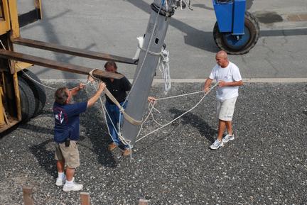
The butt end of the mast had to be supported by a forklift and moved forward slowly as the boom crane truck lifted the 1,000 lbs. The top of the mast had to be 83 feet in the air so the bottom would clear the lifelines.
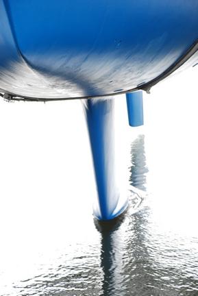
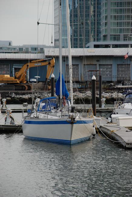
Spash Down. Ready for sea trials. Ten days later, 36 knot gusts under sail with jib up, the boat showed no sign of any problems. After hauling the keel stub interface had not cracked..
I cannot describe the sense of pride to have completed this effort. I also can't describe how I hope to never have to do this again.
The hard work paid off. Time for a barbecue for the yard crew!
CREDITS:
Such a project would not have been possible without help from many great friends.
Yann LeCun, Larry Jackel, and Alan Deeken who helped me bring the boat up the coast. Larry who helped in a number of ways on repairs.
John Strauss who bought my C&C40 and helped me on numerous occasions in the refit.
Seb Granier, Bob Malkemes, Gennady Malinsky, Larry Jackel, who dove head first to help me regularly with a number of projects from bottom paint stripping to wiring and fiberglassing.
Bill Lockwood, who runs the best yard in New Jersey, and his crew of brothers, sisters, and employees. Simply they are the best machine operators, welders, fiberglass experts, machinists, storekeepers, and office workers, the nicest and most competent yard crew I have run into.
Mike for his help in finding supplies.
My family who supported me in doing this project.
Rick van Hemmen, Naval Architect, for excellent consultations on the repairs
Ed Dubois, Naval Architect for a superbly designed boat from 1991, and his help with the new keel, and willingness to do it, eventhough much larger designs are being contracted by his firm. Michael Benakis, the engineer who designed the new keel, for producing a great looking design that seems to work well
Mars Keels, and especially Kevin Milne, for exceptionally short production time and good project management
After a typical fiberglass workday. This is why I would prefer to avoid doing a project like this again, and why I have utmost respect for those who do this work for a living...